Adjust the Photodetector
The controls on the top of the Dimension Icon scanner move the laser relative to the cantilever. Once the laser is in place on the cantilever, you must move the to obtain a good sum signal and properly orient the laser spot on the photodiode.
| |
- Verify that there is a spot visible on the Dimension Icon scanner filter screen.
|

|
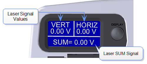
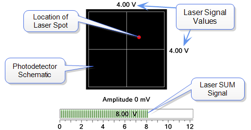
- Verify that you have an appropriate laser sum signal (greater than 0.5 V), displayed in the Dimension Icon LCD or the schematic below the video panel in the Setup view, both shown below.
|
| |
The Setup view displays the laser signal values and a schematic of the detector quadrants. The position of the laser is denoted by a red dot on the detector schematic.
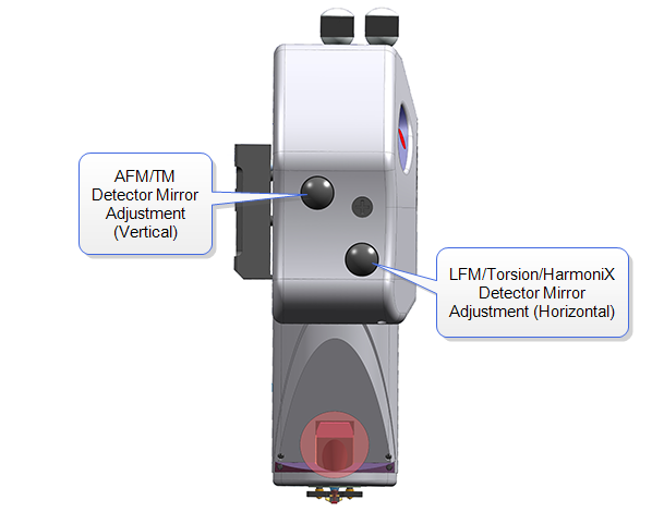
- Center the laser detector signal in the photodetector schematic using the photodetector adjustment knobs located on the left side of the Dimension Icon scanner.
|
The Vertical Deflection signal is the difference between the top and bottom photodetectors. In general, when the system is scanning, you want the laser spot centered at 0 V on the photodetector. This will provide the optimal sensitivity for detecting changes in laser spot position during scanning.
In order to achieve a centered laser spot while setting up the system in TappingMode AFM, adjust the Vertical Deflection signal to 0.
For Contact AFM, first determine an appropriate value for your sample and probe type. Adjust the Vertical Deflection signal such that the laser spot will reach 0 V on the photodetector when the setpoint is achieved.
Example: You are working in Contact mode and have determined that for your sample and probe combination you want a contact force equivalent to 2 V cantilever deflection. Set the Deflection Setpoint parameter to 0 V and adjust the Vertical Deflection to –2 V. When the system engages and deflects the cantilever by 2 V, the setpoint is reached and the laser spot will be centered vertically on the photodetector at 0 V.
Example: For a softer sample, you determine that you want a lower force of 0.5 V. Again, set the Deflection Setpoint parameter to 0 V and this time adjust the Vertical Deflection to –0.5 V. When the system engages and deflects the cantilever by 0.5 V, the setpoint is reached and the laser spot is centered vertically on the photodetector at 0 V.
NOTE: In TappingMode, the RMS amplitude (Ampl) is an AC signal and does not have any real magnitude until the cantilever tune has been completed.
NOTE: When the laser is positioned in the center of the detector schematic, the laser is also in the center of the screen on the front of the scanner. If the laser is severely out of alignment, it may help to first center the laser on the screen on the scanner using the photodetector adjustment knobs, then use the detector schematic on the image monitor to finish positioning the laser.
Previous Steps:
- Select Experiment
- Prepare and Load the Probe Holder
- Install the Probe Holder on the SPM Scanner
- Identify the Probe
- Align the Laser
Next Steps:
- Locate the Tip
- Load the sample and Focus on the Sample Surface
- If your experiment involves TappingMode, you must now Tune the Cantilever before proceeding to the next step. If you are running a Contact Mode application, continue to Check Initial Scan Parameters.
- Engage, Scan, & Withdraw
| www.bruker.com
|
Bruker Corporation |
| www.brukerafmprobes.com
|
112 Robin Hill Rd. |
| nanoscaleworld.bruker-axs.com/nanoscaleworld/
|
Santa Barbara, CA 93117 |
| |
|
| |
Customer Support: (800) 873-9750 |
| |
Copyright 2010, 2011. All Rights Reserved. |
Open topic with navigation
 to obtain a good sum signal and properly orient the laser spot on the photodiode.